| |
Arduino Oscilloscope
Description: In this tutorial, we will be making a poor man's oscilloscope using the Arduino's ADC (analog to digital converter) and rqt_plot.Tutorial Level: ADVANCED
Next Tutorial: NodeHandle and ArduinoHardware
Show EOL distros:
In this tutorial, we will be making a poor man's oscilloscope using the Arduino's ADC (analog to digital converter) and rqt_plot. We will set up a publisher which will forward the analog values from each of the Arduino's 6 ADC pins to ROS using rosserial. This will be a relatively bad oscilloscope (very low sampling frequency and resolution), but it will be perfect for many quick and dirty setups.
The code for this tutorial can be found in your Arduino IDE at File>Examples>ros_lib>ADC
If you have not done so already, make sure to clone the rosserial stack and add it to your ROS_PACKAGE_PATH.
Custom Message
This code uses a custom message type, the ADC.msg. This message has uint16 field for each of the analog input pins on the standard Arduino.
uint16 adc0
uint16 adc1
uint16 adc2
uint16 adc3
uint16 adc4
uint16 adc5
This message is a part of the rosserial_arduino package and has been added to your ros_lib library.
The Code
The code for this tutorial is fairly straight forward. The code registers a Adc msg publisher, initializes the node handle, and then tries to publish as many Adc messages as possible.
   1 /*
   2  * rosserial ADC Example
   3  *
   4  * This is a poor man's Oscilloscope.  It does not have the sampling
   5  * rate or accuracy of a commerical scope, but it is great to get
   6  * an analog value into ROS in a pinch.
   7  */
   8
   9 #include <WProgram.h>
  10 #include <ros.h>
  11 #include <rosserial_arduino/Adc.h>
  12
  13 ros::NodeHandle nh;
  14
  15 rosserial_arduino::Adc adc_msg;
  16 ros::Publisher p("adc", &adc_msg);
  17
  18
  19 void setup()
  20 {
  21   pinMode(13, OUTPUT);
  22   nh.initNode();
  23
  24   nh.advertise(p);
  25 }
  26
  27 //We average the analog reading to eliminate some of the noise
  28 int averageAnalog(int pin){
  29  int v=0;
  30       for(int i=0; i<4; i++) v+= analogRead(pin);
  31       return v/4;
  32 }
  33
  34 long adc_timer;
  35
  36 void loop()
  37 {
  38
  39     adc_msg.adc0 = averageAnalog(0);
  40     adc_msg.adc1 = averageAnalog(1);
  41     adc_msg.adc2 = averageAnalog(2);
  42     adc_msg.adc3 = averageAnalog(3);
  43     adc_msg.adc4 = averageAnalog(4);
  44     adc_msg.adc5 = averageAnalog(5);
  45
  46     p.publish(&adc_msg);
  47
  48   nh.spinOnce();
  49 }
Running the Oscilloscope
roscore
rosrun rosserial_python serial_node.py _port:=/dev/ttyUSB0
rosrun rosserial_python serial_node.py /dev/ttyUSB0
rqt_plot adc/adc0
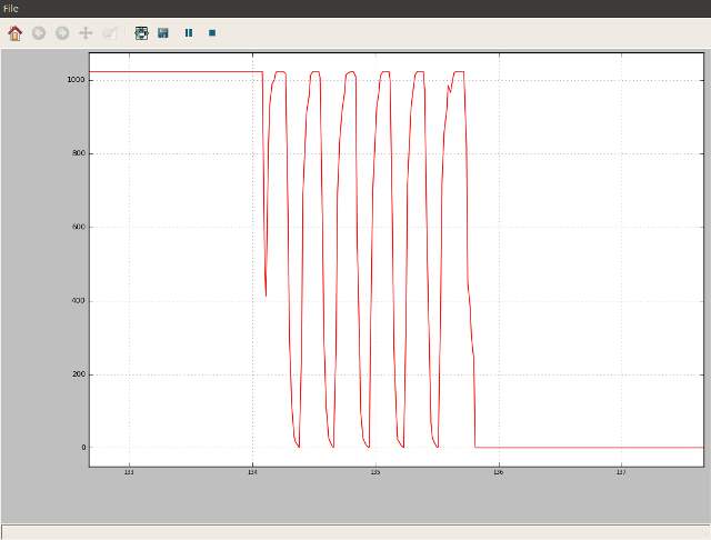
Now, you should see the raw analog value on adc0 displayed in rqt_plot. The reported readings are going to be from 0-1024 because the Arduino has a 10-bit ADC. In order to get the actual voltage, adc_val / 1024 * Arduino supply voltage. Try connecting ADC0 to ground, 5V, and 3.3V on your arduino and observing the value. Also notice that when you don't have anything connected to the ADC, it is a floating analog input and its value will oscillate randomly.
For example, look at the below output where the ADC0 input is switched between 5V and gnd. There are wild oscillations during the transition.


